
v 1.0.0 03JUL26
SCOUT43
EMOTO / SURRON ULTRA BEE
USER MANUAL
USER MANUAL

THANK YOU FOR CHOOSING RACINGBROS!
For safety and performance, follow this manual during installation and setup. Regular servicing by authorized centers is recommended.
PREPARATION

Remove all accessories and remove the OEM front fork assembly from the bike.
TOOLS REQUIRED FOR SCOUT43 INSTALLATION
The following tools and materials are required for installation:
- Torque wrench
- Hex keys (4 mm, 5 mm, 6 mm, 8 mm, and 12 mm)
- Assembly grease
- Blue threadlocker (such as Loctite® 243)
- Phillips screwdriver
TOOLS REQUIRED FOR SCOUT43 INSTALLATION
The following tools and materials are required for installation:
- Torque wrench
- Hex keys (4 mm, 5 mm, 6 mm, 8 mm, and 12 mm)
- Assembly grease
- Blue threadlocker (such as Loctite® 243)
- Phillips screwdriver
INSTALLATION
STEP 1
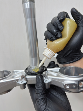
Thoroughly pack both the upper and lower headset bearings with a high-quality waterproof grease.
STEP 2
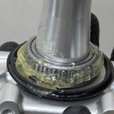
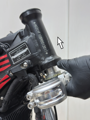
Install the lower triple clamp and steerer tube assembly into the head tube as shown.
STEP 3
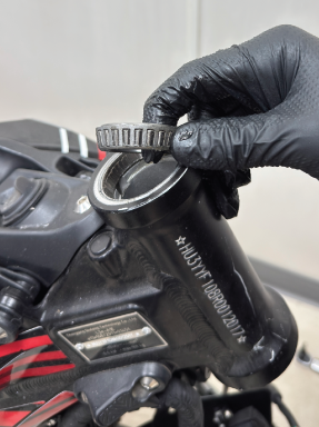
Retain the OEM headset bearings and remove any old grease, dirt, or debris before reinstallation.
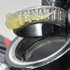
Apply a generous amount of fresh grease to the upper headset bearing.
Apply a generous amount of fresh grease to the upper headset bearing.
STEP 4
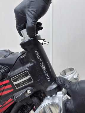
Thread the steering adjustment nut onto the steerer tube.
Tighten the nut only enough to remove play from the steering assembly while ensuring smooth, friction-free steering movement.
Tighten the nut only enough to remove play from the steering assembly while ensuring smooth, friction-free steering movement.
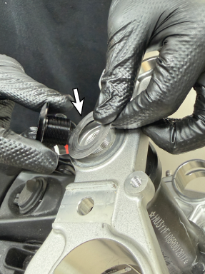
STEP 5
Install the upper triple clamp and steerer tube top cap.
Ensure that the OEM spacer is reinstalled in its original position.
Ensure that the OEM spacer is reinstalled in its original position.
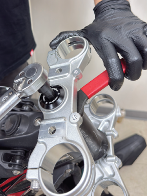
STEP 6
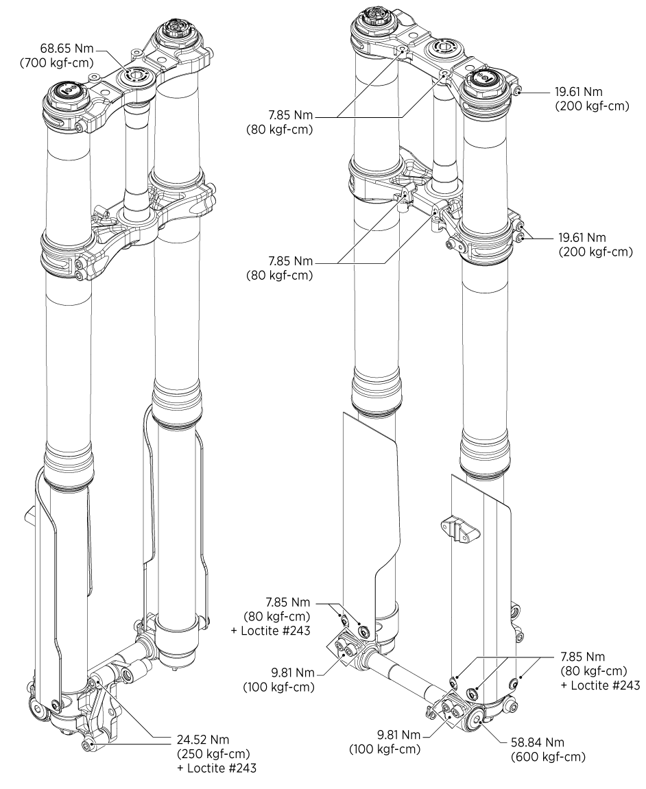
Torque the steering cap to 68.65 Nm (700 kg-cm).
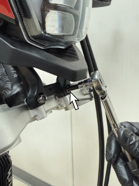
STEP 7
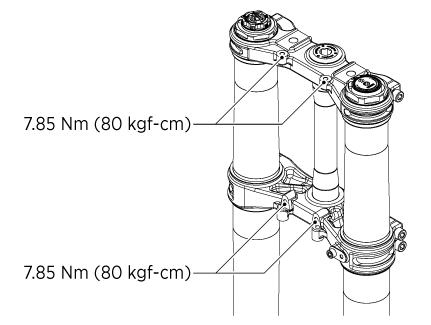
Install the four upper clamp mounting bolts and tighten them to 7.85 Nm (80 kg-cm).
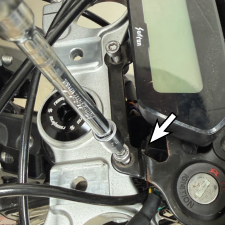
STEP 8
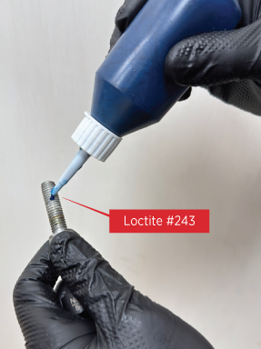
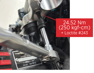
Apply blue threadlocker to the handlebar clamp bolts.
Position the handlebars as desired and tighten the clamp bolts to 24.52 Nm (250 kg-cm).
Position the handlebars as desired and tighten the clamp bolts to 24.52 Nm (250 kg-cm).
STEP 9
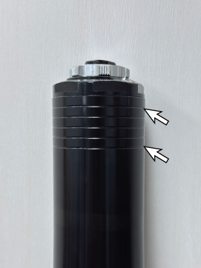
Adjust the handlebar risers to the desired height and tighten all fasteners securely. Height adjustment markings are spaced at 5 mm intervals.
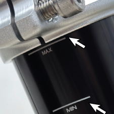
Note:
When using a 21-inch front wheel, the fork tubes must be positioned at the maximum height setting, with the tops of the fork tubes flush with the upper triple clamp.
When using a 21-inch front wheel, the fork tubes must be positioned at the maximum height setting, with the tops of the fork tubes flush with the upper triple clamp.
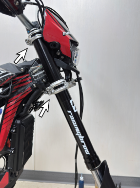
STEP 10
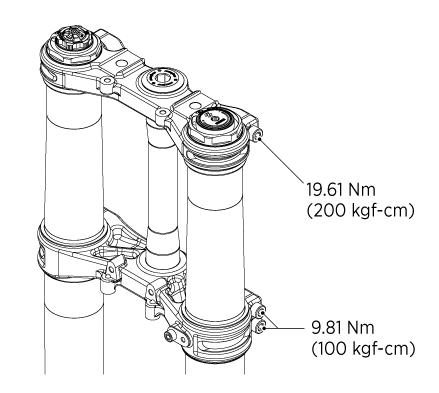
Clean the outer fork tubes to remove any oil, dirt, or debris. Slide the fork legs upward into the triple clamps and position them at the desired height. Tighten all triple clamp pinch bolts to the specified torque values.
STEP 11
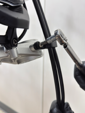
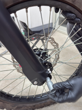
Route the front brake hose and wheel speed sensor wire through the fork guard guide. Secure the guide using the supplied M6 bolts and a 5 mm hex key. Tighten the bolts by hand at this stage.
STEP 12
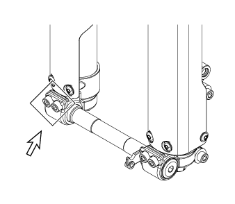
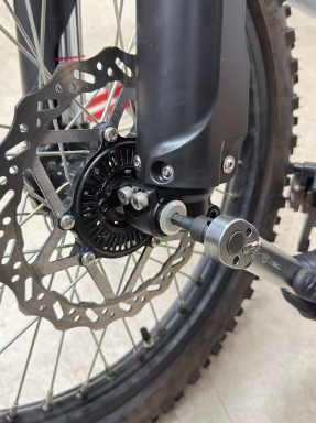
Install the front axle through the wheel assembly. If necessary, temporarily tighten the non-brake-side axle pinch bolts to hold the axle in position while tightening the axle nut.
STEP 13
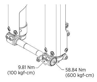
Torque the front axle nut to 58.84 Nm (600 kg-cm). Torque the brake-side axle pinch bolts to 9.81 Nm (100 kg-cm).
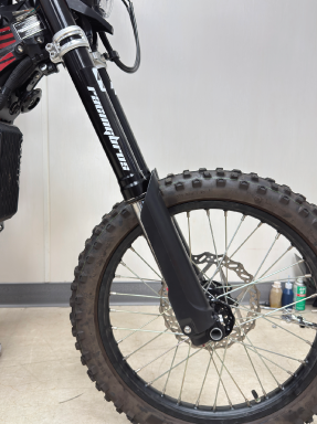
STEP 14
Align the fork legs to prevent fork binding. Remove the motorcycle from the stand and place it on level ground. Apply the front brake and firmly compress the front suspension several times. This allows the non-brake-side fork lug to float and self-align correctly on the axle.
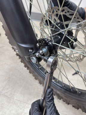
STEP 15
After the fork legs have been aligned, move to the non-brake side of the motorcycle and tighten the axle pinch bolts to the specified torque value. Alternate between the bolts while tightening to ensure even clamping force.

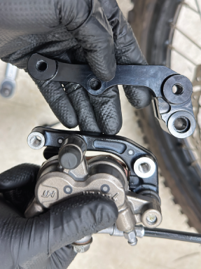
STEP 16
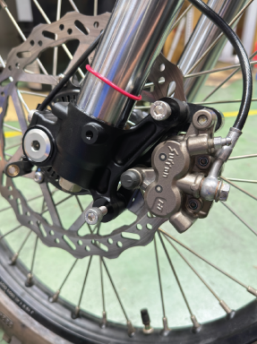
When using the OEM brake caliper, remove the original caliper adapter bracket. Transfer the sliding pin and rubber boot from the OEM bracket to the caliper adapter bracket supplied with the SCOUT43 kit.
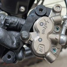
STEP 17
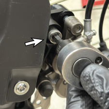
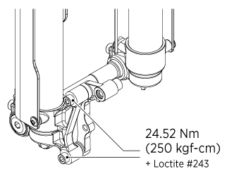
Install the brake caliper and apply blue threadlocker to the mounting bolts.
Torque the caliper mounting bolts to 24.52 Nm (250 kg-cm).
Torque the caliper mounting bolts to 24.52 Nm (250 kg-cm).
STEP 18
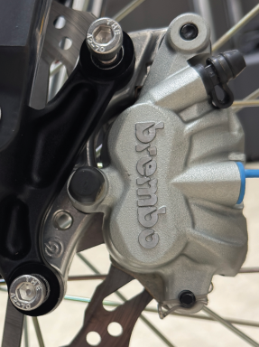
For improved braking performance, SCOUT43 is compatible with premium motocross brake calipers featuring 95 mm mounting bolt spacing.
These calipers install directly onto the SCOUT43 system without additional adapters.
These calipers install directly onto the SCOUT43 system without additional adapters.
MOUNT
CENTER
CENTER
95
mm
TUNING
PRE-LOAD

Suspension pre-load adjustment is vital, affecting bike height and front fork angle. Rider weight compresses shock absorbers, causing sag. Measure bike height fully extended (A) and compressed with rider (B). 60±10mm is recommended.
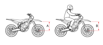

PRELOAD
10
mm
* 1 click = 1mm
COMPRESSION DAMPING
Turn the knob clockwise by 4 clicks, then retest. If it feels excessive, make a 1-click counterclockwise adjustment.
When riding on rough, bumpy roads with harsh impacts, reduce compression damping.
Begin by turning counterclockwise: 4 clicks initially, then 2 as needed.
When riding on rough, bumpy roads with harsh impacts, reduce compression damping.
Begin by turning counterclockwise: 4 clicks initially, then 2 as needed.
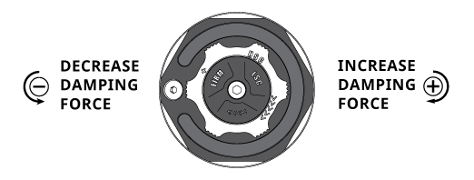


When it's bumpy, rough, or harsh, turn the compression counterclockwise.

When it's unstable, loose, or bouncy, tighten compression clockwise.
HIGH-SPEED
COMPRESSION
COMPRESSION
12
CLICKS
LOW-SPEED
COMPRESSION
COMPRESSION
16
CLICKS
Compression damping regulates the speed of shock absorber compression, influencing braking dive, traction, and ride feel. Proper settings enhance tracking and performance. To achieve a lower riding position, smoother bike sinking, or softer corner entry, increase compression damping.
REBOUND
Rebound damping manages shock absorber bounce-back speed after compression, adjusted based on factors like rider style, weight, preference, and road conditions. Faster rebound suits stable conditions; slow it by clockwise damping increase. To enhance speed, reduce damping counterclockwise.

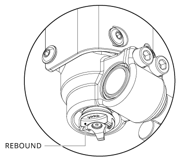

When it's bumpy, turn the rebound counterclockwise for a quicker response.

When it's unstable, loose, or bouncy, tighten rebound clockwise for a slower response.
REBOUND
21
CLICKS
For unstable, bouncy motorcycle handling, up the rebound damping. Turn the knob 4 clicks clockwise, then retest. If too harsh, adjust by 2 counterclockwise clicks. On pothole-laden roads, cut harshness by decreasing rebound damping. Turn counterclockwise: 4 clicks initially, then 2 as needed.
Fine-tuning compression damping based on road conditions and riding style allows for the most comfortable and optimal setup. As your sensitivity to suspension behavior improves, try making more precise adjustments.
Fine-tuning compression damping based on road conditions and riding style allows for the most comfortable and optimal setup. As your sensitivity to suspension behavior improves, try making more precise adjustments.
ADJUSTABLE HYDRAULIC BOTTOM-OUT
RACINGBROS Adjustable Hydraulic Bottom-Out (RHBO) uses a dedicated hydraulic bottom-out chamber and piston to provide tunable bottom-out resistance. A 4 mm adjuster controls oil flow through the hydraulic bottom-out circuit and offers 12 clicks of adjustment, from fully open (minimum bottom-out resistance) to fully closed (maximum bottom-out resistance).
HYDRAULIC
BOTTOM-OUT
BOTTOM-OUT
12
CLICKS
As the fork approaches full compression, the piston enters the hydraulic bottom-out chamber and forces oil through the adjustable port. Closing the adjuster restricts oil flow, increases chamber pressure, and provides greater damping during the final 10% of fork travel.

TECHNICAL DRAWING

FORK SPRING GUIDE
| Rider weight | Fork spring rate | Product number |
|---|---|---|
| 121–165 lb (55–75 kg) | 8 N/mm (45.7 lb/in) | R3050210 |
| 154–198 lb (70–90 kg) | 9 N/mm (51.4 lb/in) | R3050211 |
| 187–231 lb (85–105 kg) | 10 N/mm (57.1 lb/in) | R3050212 |
| 220–265 lb (100–120 kg) | 11 N/mm (62.8 lb/in) | R3050213 |
* Rider weight: Total rider weight including all riding gear and protective equipment.
!
WARNING
Modifying suspension settings can significantly alter handling characteristics and may overload components if changes are extreme.
· Only make adjustments within the recommended range.
· After adjustments, ride slowly at first to get accustomed to the new handling.
Failure to comply with the manual may result in product failure, damage, property loss, or personal injury. Damage caused by tampering with or modifying chassis components is not covered by the warranty.
· Only make adjustments within the recommended range.
· After adjustments, ride slowly at first to get accustomed to the new handling.
Failure to comply with the manual may result in product failure, damage, property loss, or personal injury. Damage caused by tampering with or modifying chassis components is not covered by the warranty.
INTENDED USE
This RACINGBROS suspension component is specifically designed for use in closed-course racing environments with approved vehicles. Any misuse, including the use of non-specified fluids or improper applications, will compromise safety and performance.
MAINTENANCE AND WARRANTY
To maintain warranty coverage and ensure optimal performance, all service work must be carried out at a RACINGBROS Authorized Center, using only RACINGBROS-approved parts and accessories. The use of non-approved parts will void the warranty.
INSTALLATION AND TORQUE
The suspension component must be installed according to the vehicle manufacturer's specifications. It is recommended that installation be performed by a RACINGBROS Authorized Center, adhering to the correct torque settings.
ENVIRONMENTAL RESPONSIBILITY
All used fluids, lubricants, and components must be disposed of responsibly, in accordance with local environmental regulations.
CUSTOMER ASSISTANCE
For any questions or support regarding your RACINGBROS suspension, please contact a RACINGBROS Authorized Center or visit the RACINGBROS website: www.racingbros.com

